All published articles of this journal are available on ScienceDirect.

Large Diameter Femoral Heads Impose Significant Alterations on the Strains Developed on Femoral Component and Bone: A Finite Element Analysis
Authors Info & Affiliations
Abstract
Total Hip Arthroplasty aims at fully recreating a functional hip joint. Over the past years modular implant systems have become common practice and are widely used, due to the surgical options they provide. In addition Big Femoral Heads have also been implemented in the process, providing more flexibility for the surgeon. The current study aims at investigating the effects that femoral heads of bigger diameter may impose on the mechanical behavior of the bone-implant assembly. Using data acquired by Computed Tomographies and a Coordinate Measurement Machine, a cadaveric femur and a Profemur-E modular stem were fully digitized, leading to a three dimensional finite element model in ANSYS Workbench. Strains and stresses were then calculated, focusing on areas of clinical interest, based on Gruen zones: the calcar and the corresponding below the greater trochanter area in the proximal femur, the stem tip region and a profile line along linea aspera. The performed finite elements analysis revealed that the use of large diameter heads produces significant changes in strain development within the bone volume, especially in the lateral side. The application of Frost’s law in bone remodeling, validated the hypothesis that for all diameters normal bone growth occurs. However, in the calcar area lower strain values were recorded, when comparing with the reference model featuring a 28mm femoral head. Along line aspera and for the stem tip area, higher values were recorded. Finally, stresses calculated on the modular neck revealed increased values, but without reaching the yield strength of the titanium alloy used.
INTRODUCTION
In reconstructive orthopaedics, total hip arthroplasty (THA) is an extremely successful practice. Nowadays modular hip implants systems are more frequently used due to their available restoration options for anteversion and offset, combined with excellent clinical results [1, 2]. Additionally Big Femoral Heads (BFH) have been implemented, aiming at diminishing phenomena such as dislocation and impingement [3, 4].
However currently, the implant stability and longevity are the most important issues in THA [5]. One of the factors that may compromise the integrity is stress shielding occurring after the implant insertion [6], leading to stress and strain alterations within the femur and finally to bone remodeling and absorption [7], especially for cementless implants [8].
Several studies with extensive experimental background [9, 10] have dealt with the in vivo determination, of physiological strain values on femurs and the investigation of bone remodeling, with the use of strain gauges [11, 12], validating the hypothesis of H.M. Frost [13], that developed strains impose bone growth - absorption activity.
Similarly, the strains and stresses developed after THA [14] are being investigated. Using either photoelasticity methods [15], or testing with composite femurs [16], press-fitted implants have displayed an overall positive response to the applied loading. Some strain concentrations or areas displaying a drop in strains have been revealed and investigated [17, 18], since the appearance of osteopenia may lead to clinical problems [19].
To this end, Finite Element Analysis (FEA) has become a standard method in analyzing and predicting the strain and stress patterns in THA [20]. Correlation of FEA with bone density and DEXA data has led to a number of studies [21]. Only recently, modular implant systems have been implemented in FEA studies, mainly examining the influence of version, offset and press-fit fixation with respect to load transfer parameters [1, 22]. Regarding BFH, the safe range of motion and the stress fields in the acetabulum are being researched [23, 24]. The current study aims at investigating the effect that bigger (36mm, 46mm, 56mm) femoral heads may impose on the stress and strain fields of the bone implant assembly in comparison with a typical femoral head of 28mm.
MATERIALS AND METHODS
For the study of the mechanical behavior of a THA using different modular femoral head components, the Finite Element Method was chosen: a model was generated based on CT data for the femur and loading scenarios, as found in literature, were applied. For the performed analyses, the recorded strains and stresses are illustrated in appropriate plots and figures, focusing on several areas of interest and clinical importance.
Bone Geometry
A cadaveric femur (35 years old, male, left femur), was selected from a collection at the University of Athens, Greece, Dpt of Anthropology. CT scans of the femur were acquired in digital format (DICOM) on a Siemens SOMATOM Sensation4 CT Scanner. Slice thickness was set to 1mm. Using Materialise Mimics v.8 each CT scan was individually processed providing data for the full femur geometry. The resulting three-dimensional CAD model was generated after further processing through Geomagic Studio v.9 and finally imported into SolidWorks 2008.
Profemur-E Implant System
For the study at hand, the Profemur-E ®, Wright Medical Memphis TN, total hip arthroplasty implant system was chosen due to its extensive modularity and intraoperative assembly options. Based on a preoperative planning for the femoral implant [25] - by superimposing the Profemur-E templates on the axial X-ray of the anteroposterior plane of the femur - a size 5 was selected. In order to isolate the head modularity influence, only a long straight neck from the Profemur product series was selected. All parts of the implant were scanned by a Coordinate Measurement Machine (CMM), a Mistral 07075 by DEA-Brown & Sharpe Inc. with a Renishaw PH10M scanning head in compliance with the ISO 10360-2 standard and were afterwards digitized (Fig. 1a).
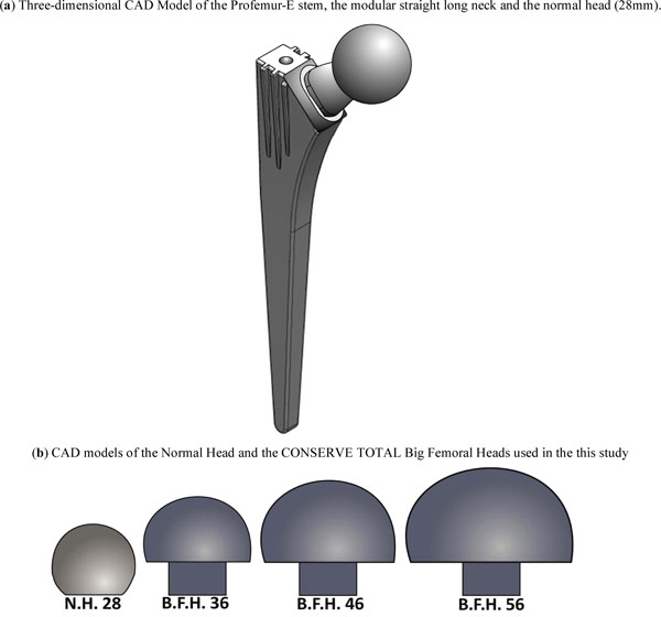
Three-dimensional CAD models of the modular implant system and the big femoral heads.
The femoral heads chosen were: a standard femoral head with a typical diameter of 28mm, without any offset and three big femoral heads of the Conserve Total® Head series by Wright Medical®. Their diameters were 36mm, 46mm and 56mm respectively (Fig. 1b), again with no additional offset.
Finally the osteotomy was performed; the stem was aligned/oriented and finally inserted into the bone volume. The implementation of the modular neck and the four different femoral heads created the final mathematical models.
Finite Element Analysis
The transition from the CAD environment to the FEA was accomplished through the GUI of ANSYS Workbench V.11 SP1.0, where the models were natively imported from SolidWorks 2008. Using the integrated mesh generator a high quality finite element mesh consisting of approximately 186.000 ten-node tetrahedral elements, was generated (Fig. 2). The contacts between the different parts of the three-dimensional model were considered as bonded, but with the possibility to undergo minor relevant movement without separation of faces in contact, as the “no separation” option in ANSYS Workbench denotes.
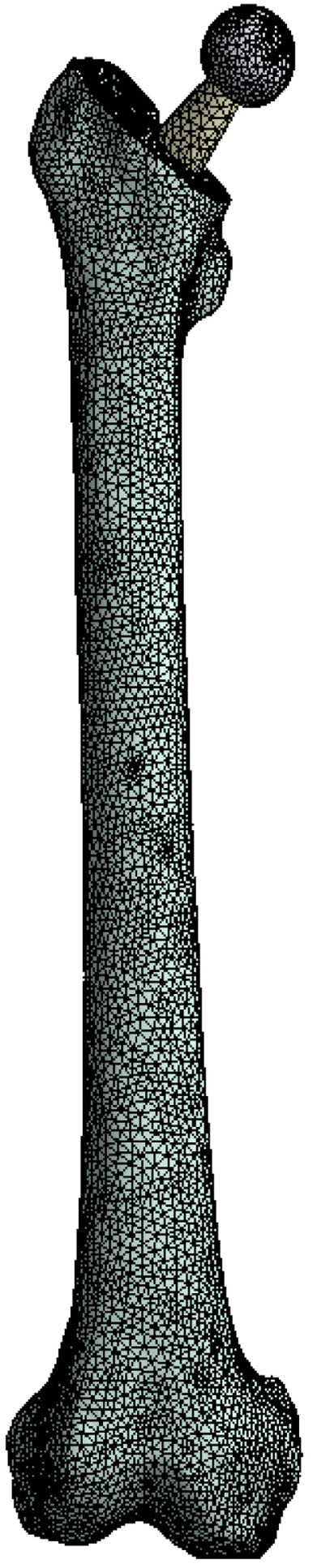
Tetrahedral finite element mesh of the full assembly.
Materials & Loading
For all materials used in the finite element analysis, linear, elastic, isotropic properties - with homogenous distribution - were assigned [26]. At this point it is clarified, that a more accurate approximation of the bone properties would be an anisotropic material distribution, which is an issue of ongoing research by the authors. The modulus of elasticity for the bone volume was set to EBONE,1 = 17000 MPa for the cortical bone (Hounsfiled Units: from 3071 to 368), EBONE,2 = 1000 MPa for the cancelous (Hounsfiled Units: from 368 to -741) and finally the Poisson ratio νBONE = 0.30 [27, 28]. Based on technical specifications for the Profemur-E THA system, the following materials were used: Ti-Alloy Stem with ESTEM= 114 GPa, νSTEM = 0.35, Ti-Alloy Neck with ENECK = 114 GPa, νNECK = 0.35, normal femoral head ENH= 200 GPa, νNH = 0.3 and big femoral head with EBFH= 208 GPa, νBFH = 0.3.
According to previous studies [29, 30] the stance phase of the gait cycle was simulated and two main forces were applied on the finite element model. The first one, with a magnitude of 2450 Newton, was implemented on each modular head, on an area relevant to the corresponding cup, and represented the body weight transferred to the head through the acetabulum socket. Forces from the main muscle groups - gluteus minimus, medius and maximus - were applied as a single resultant force of 1650 Newton, on the upper boundary of the greater trochanter area. Both forces were applied on small areas - not on a single point - in order to avoid stress concentration phenomena. According to the knee joint anatomy, the lower area of the femur bone, namely the lateral and medial condyle surface along with the patellar surface, were fully constrained.
RESULTS
The Profemur-E stem is a press-fitted stem with a grit-blasted surface, and is positioned without the use of acrylic cement, thus leading to the investigation of the von Mises strain, especially used in design work because it allows any arbitrary three-dimensional stress state to be represented as a single positive value, distribution in the upper region of the femur [31]. At this point it should be mentioned that the presentation of results is focused on the three dimensional nature of our finite element model. The abovementioned regions of clinical interest have been setup according to the clinical presentation of Gruen zones [32]. Therefore the calcar area (as described by the Gruen zones 7 A-P View & 8, 14 Lat View), approximately 15mm below the osteotomy plane, at the medial side of the femur (Fig. 3B), and the corresponding region below the greater trochanter (as described by the Gruen zones in the lower region of zone 1, zone 2 and upper area of zone 3), at the lateral side (Fig. 3A) of the bone [33] were isolated due to their clinical importance for the result analysis. Along linea aspera, the geometrical extension of the calcar and the lesser trochanter, a profile line was chosen (Fig. 3C) (through Gruen zones 7 A-P View & 13,12,11 Lat View). It is believed by the authors, that strains along this path may reveal significant information regarding the influence of BFH on the length of the femoral shaft. The von Mises strains on the area surrounding the distal stem tip (Fig. 3D) were also examined (Gruen zones 4 A-P View & 11 Lat View), since this area is considered to be connected with postoperative thigh pain phenomena [34, 35]. The equivalent von Mises stress on the titanium alloy modular necks was finally investigated, since the implementation of BFH revealed significant alterations.
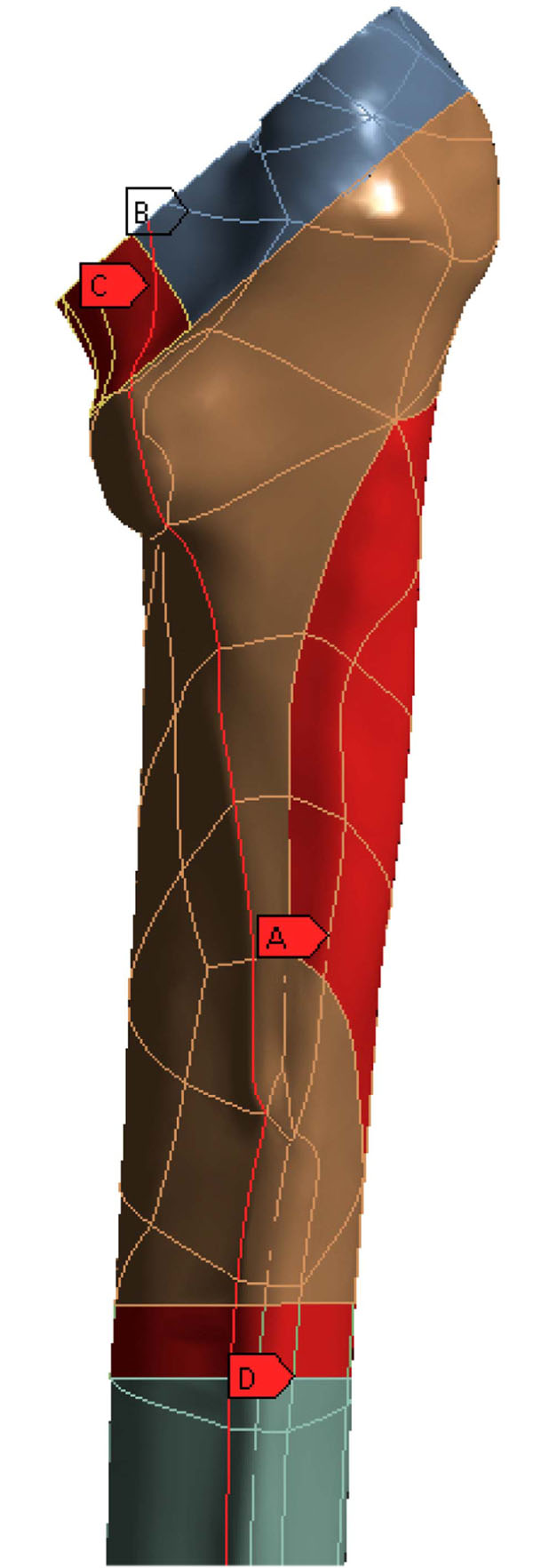
Areas of clinical interest. A) Lateral region, below the greater trochanter [Gruen zones 1,2,3], B) Calcar region, 15mm below the osteotomy plane [Gruen zones 7,8,14], C) Profile line along linea aspera [through Gruen zones 7,13,12,11] and D) Cortical Bone region at the stem tip [Gruen zones 4,11].
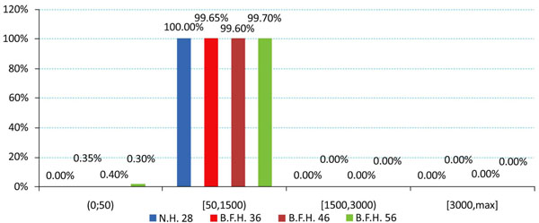
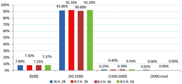
For the bone volume, the strain values for each model and region were grouped together according to Frost’s - a modern expression of Wolff’s Law [36] - boundaries for bone absorption/remodeling [13,37]. As mentioned, the strain value, εFEM,i, for each node on the models was recorded and categorized based on the following table (Table 1):
Strain Values (µstrains) Classification According to Frost’s Law
| Below 50 µstrains | Disuse zone | New bone is not developed normally, loss of bone occurs |
| 50 µstrains → 1500 µstrains | Adaptive zone | Bone conservation, tend to equal but not exceed the amount resorbed, healthy active growing |
| 1500 µstrains → 3000 µstrains | Mild overload zone | Bone strengthening, changes in its architecture where and as needed to lower its strains, healthy active growing |
| Above 3000 µstrains | Overload zone | Peak Strains lead to bone growth, may or may not be positive |
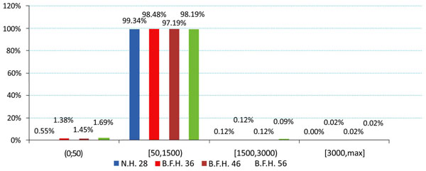
The produced charts (Figs. 4-6) provided information regarding the bone remodeling activity imposed by the strains developed. At the region below the greater trochanter (Fig. 4) it was clearly visible that strains were causing bone remodeling. It yielded that, without overload, the bone tissue tends to compensate for the acting loads by remodeling and only a slight percentage dropped below the disuse limit. However, as far as the calcar is concerned (Fig. 5), a significant percentage of approximately 7.5% (mean value) belonged to the disuse zone. This denoted that strains developed by the modular implant and the femoral heads may - in some small regions - invoke bone absorption. As far as the stem tip is concerned (Fig. 6), only 1.5% of the nodes displayed bone strains in the disuse zone. A very small percent was also located at the 1500 - 3000 μstrains zone, which was correlated with the area in direct contact with the stem tip.
The investigation of the maximum values, omitting the region where the muscle force was applied, in comparison with the typical head of 28mm, revealed that the use of BFH imposed an overall increase in strains and stresses.
However, in the calcar region a drop towards the reference model was recorded. With percentages 5.51% (36mm), 6.64% (46mm) and 7.01% (56mm) it was revealed that the strains on the medial side were influenced (Fig. 6 - Calcar). On the other hand, a relevant increase - 8.53%, 9% and 10.12% respectively - was noted in the lateral side, below the greater trochanter (Fig. 7 - Greater Trochanter), strengthening the theory that upon normal loading extension occurs, whereas flexion is present at the calcar. As shown in Fig. (9, left column) the distributions were also altered.
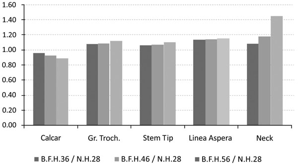
Maximum strain values (in MPa) with respect to the typical head for a) the calcar, b) the region below the greater trochanter, c) the linea aspera d) the stem tip region and e) maximum stress for the modular neck.
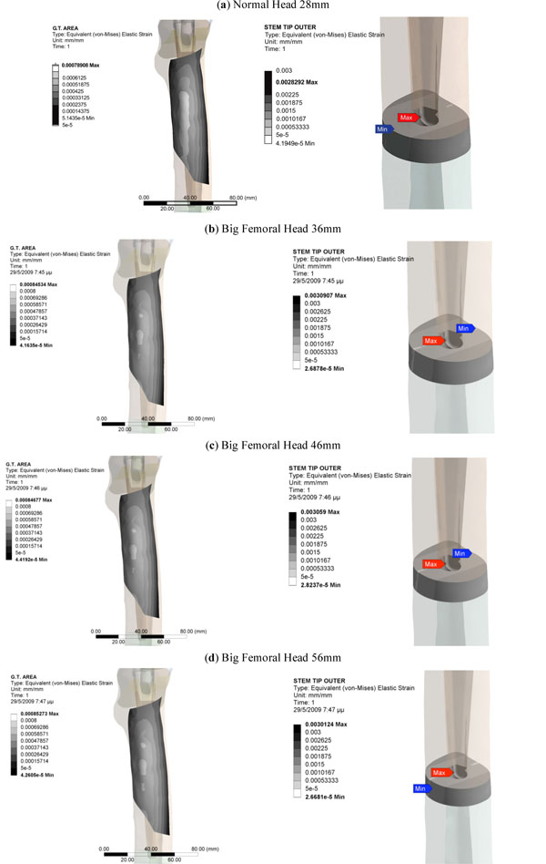
Equivalent Von Mises Strains on the area below the greater trochanter (left column) and on the region around the stem tip (right column).
Similar results were also recorded for the stem tip area (Fig. 9, right column). The 36mm BFH invoked a 15.43% rise in the developed strains in the cortical bone around the stem tip (Fig. 7-Stem Tip). For the 46mm and the 56mm femoral heads alterations of 16.82% and 17.39% were revealed, denoting that by increasing the head diameter, strains rise.
As already mentioned, a profile line along linea aspera was isolated and the corresponding results are illustrated in Fig. (8). More specifically, the main alterations in strains were registered for the distal part of the femur, below the isthmus (z= 210mm). For the stem tip (z=230mm to z=250mm) (Gruen zone 11) the maximum differences appeared with an approximate mean value 18.29% percent for all cases. Moving towards the femur metaphysis (z=260mm to z= 335mm) (through zones 12, 13) the BFH models showed increased strains compared to the reference model but near the lesser trochanter (zone 7) all lines converged and the values dropped below the 50μstrains disuse limit, marking possible bone absorption (z=340mm to z= 360mm).
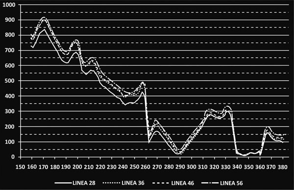
Recorded µstrains along linea aspera. The vertical axis illustrates the recorded µstrains, and the horizontal axis the vertical coordinate of the nodes located on the profile line. For z=380mm the osteotomy plane is reached.
The rather high percentages (Fig.7-Linea aspera) (16.31% for 56mm, 18.29% for 46mm and 19.34% for 36mm) finally revealed that the implementation of BFH yielded an increase in strains along this profile and therefore supported the original assumption that linea aspera is highly influenced by the different head diameter, thus leading to rather increased remodeling activity.
From the FEA qualitative and quantitative information regarding the mechanical behavior of the titanium alloy modular neck was finally derived. Omitting the extreme peak values found at the contact areas, it was shown that the usage of BFH altered significantly the stress distributions and values developed throughout the neck volume. An increase of 13.87% was recorded for 36mm head, 20.93% for the 56mm and 43.62% for the 56mm head, denoting that the increase of head diameter imposes a malignant loading scenario on the long modular neck (Fig. 7-Neck). For the three models using BFH, higher values were recorded at the distal end of the 12/14 Morse taper of the neck along with increased stresses (Fig. 10) found at the narrow part right under the taper, creating thus a region under substantial loading, but within the material’s yield strength. As far as the neck region collaborating with the stem is concerned all models had the same behavior with very low stress values (Fig. 10), which was expected due to the contact limitations applied.
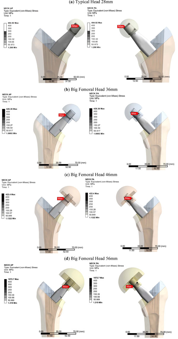
Modular Straight Long Neck, Profemur Series. Equivalent Von Mises Stress Distributions anteriorly (left) and posteriorly (right).
DISCUSSION & CONCLUSIONS
The purpose of this study was to investigate the biomechanical influence of the bigger femoral head diameters combined with an appropriate commercial modular total hip arthroplasty system on the bone-implant assembly. It is without doubt that modular hip implants provide the medical team with a variety of solutions [38] and that implementation of BFH in THA operations aims to provide further options and, in the same time, diminish postoperative complications, such as dislocation and impingement. This research revealed that the stress and strain distributions within the implants and the femur were directly associated with the bigger head diameters.
For the study at hand the FEA was chosen, since it is a highly validated method [21], with accurate results, despite the several simplifications that are being applied. At first it should be noted that the current finite element model had not been validated against experimental data [20]. For the bone volume only two linear elastic isotropic materials were assigned, which does not respond to the actual bone structure [26]. Finally, a thorough analysis on the forces applied on the femur with respect to modular necks and BFH has yet to be established. It was, therefore, decided to use the same loading scenario for all cases, as commonly found in literature [30].
For the calcar region a drop in strain values was established, revealing possible bone absorption that may influence implant stability [6, 22]. This was counterbalanced by the increased strains in the lateral proximal femur [9]. Higher strain values on the stem tip area may signify an elevated possibility for thigh pain [34] in the long term, but the current values - assuming the short postoperative period - were within the limits of 50μstrains and 3000μstrains for healthy bone growth. Approximately 91 - 93 percent of the total femur volume was included in the two middle zones of healthy remodeling activity. The majority belonged to the adaptive zone and a small percent to the mild overload zone, located mainly at the stem-bone interface, where bone remodeling appears as a result of the implant insertion and its after-effects [18, 39, 40]. A very small percent of 0.05%, displayed strain values in the overload zone. The majority of the nodes belonging in the disuse zone, were directly correlated with the nodes in the distal part of the femur that are fully fixed, but several nodes with the full volume - mainly in the calcar - had strains below the 50 μstrains limit.
Finally an increased loading environment was discovered for the long straight modular neck - especially for the 56mm head - but the equivalent von Mises stress was well below the yield strength of the titanium alloy used.
Concluding, the finite elements analysis confirmed the original hypothesis that big femoral heads posed significant changes in strains and stress developed on the femur and the femoral implant components, thus setting ground for further research studies towards this direction.
CONFLICT OF INTEREST
There are no conflicts of interest.
ACKNOWLEDGEMENTS
This paper is part of the 03ED292 research project, implemented within the framework of the “Reinforcement Programme of Human Research Manpower” (PENED) and co-financed by National and Community Funds (25% from the Greek Ministry of Development-General Secretariat of Research and Technology and 75% from E.U.-European Social Fund).
The cadaveric femur originates from a collection of the Department of Anthropology, in University of Athens, under Dr. Sotiris Manolis.
The Hip Implant System was provided by “Orthomedical Ltd”, authorized company for orthopedic implants and medical equipment.