All published articles of this journal are available on ScienceDirect.

Total Hip Prostheses in Standing, Sitting and Squatting Positions: An Overview of Our 8 Years Practice Using the EOS Imaging Technology
Authors Info & Affiliations
Abstract
More total hip arthroplasty (THA) is performed worldwide and especially in younger and more active patients compared to earlier decades. One of the focuses of THA research in the future will be on optimizing the radiological follow-up of these patients using 2D and 3D measurements of implants position while reducing the radiation dose delivered.
Low-dose EOS® imaging is an innovative slot-scanning radiograph system providing valuable information in patient functional positions (standing, sitting and even squatting positions). EOS has been proven accurate and reliable without significant inconvenience caused by the metallic artifacts of implants. The ability to obtain precise data on implant orientation according to the patient posture opens new perspectives for a comprehensive analysis of the pelvic frontal and sagittal balance and its potential impact on implants function and failures.
We report our 8 years experience on our first 300 THA patients using this technology routinely for pre and post op evaluation. Our results will be compared and confronted with the actual literature about this innovative technology. We shall especially emphasize our experience about patients with abnormal posture and the evolution of the subject over time, because the phenomenon of an aging spine is frequently associated with the process of aging hips.
INTRODUCTION
More total hip arthroplasty is performed in younger and more active patients compared to earlier years. The focus of adult reconstruction research in the future will be on extending the durability and survivorship of the implants and optimizing the radiological follow-up of these patients as loosening, osteolysis, wear and dislocation persist as potential complications. Another objective is the detection of patients at risk for complications and the optimization of planning to reduce the incidence of implant malposition and leg-length discrepancy. It is also important to better understand and manage other intricate orthopedic disorders in patients who undergo THA (scoliosis, sagittal and frontal imbalance), because these disorders may affect the surgical outcome and complication rate. Most radiographic analyses of THA patients are based on anteroposterior (AP) radiographs in the standing position and computed tomography (CT) scans in the lying position. Despite its better accuracy, CT imaging cannot be routinely performed because it is expensive and exposes the patient to more radiation. Moreover, CT must be performed in the supine position. Recent literature expresses potential interest in standing and sitting radiographs and the importance of lateral evaluation of THA in these functional situations [1, 2]. Variations in pelvic parameters that are commonly measured in spine surgery (pelvic tilt PT, sacral slope SS and pelvic incidence I) [3] and changes in the orientation of the anterior pelvic plane APP (the Lewinnek plane) [4] are relevant parameters for planification and navigation as they significantly modify the prosthetic hip biomechanics [5]. In addition, these data appear to be important during the course of THA follow-up [6-8].
The EOS® system (EOS Imaging, Paris, France) is an innovative slot-scanning radiograph system allowing the acquisition of radiograph images while the patient is standing, sitting or even squatting with less irradiation than standard imaging (Fig. 1). This technology is based on studies of gaseous detectors by Georges Charpak, who won the Nobel Prize in physics in 1992 [9]. EOS was originally used in the peri- and postoperative management of idiopathic scoliosis considering the need for repeated radiographs and the importance of limiting the radiation dose [10]. Spinal deformities can be studied in standing position with AP and lateral radiographic images of equivalent quality in all sections of the spine and furthermore, three-dimensional (3D) models using the Stereos® software [11].
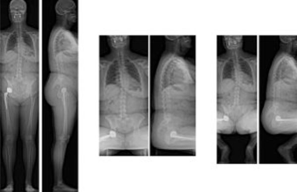
Simultaneous AP and lateral EOS images in standing sitting and squatting positions.
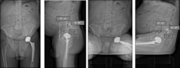
Changes in SS and PT according to the standing or sitting position. “I” is an anatomical (morphological) angle and then no modification are observed between standing and sitting positions. From standing to sitting position, the lumbar lordosis reduces, and the lumbar spine becomes more flat according to the modification of the pelvic tilt. SS reduces in sitting position while PT increases.
Significant outliers can be observed. In this case, a moderate hip flexion can be observed in standing position. For sitting position, the hip flexion is very limited: pelvic extension is needed as a compensation (we can observe a simultaneous and coherent spinal kyphosis).
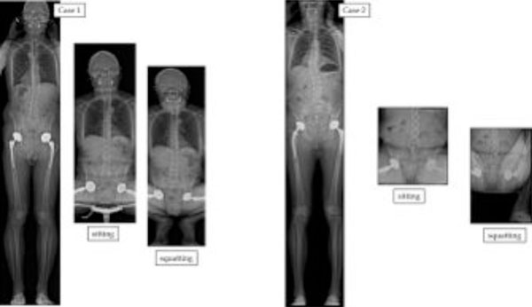
Standing sitting and squatting positions: the difference in SS corresponds to the available flexion of the lumbo-sacral junction (available extrinsic pelvic flexion), as distinct from potential hip-joint flexion (available intrinsic pelvic flexion). In the squatting position, pelvic extension is increased (case 1). Due to the limitation of hip flexion in some individuals, the positioning of the hips can be asymmetrical (case 2).
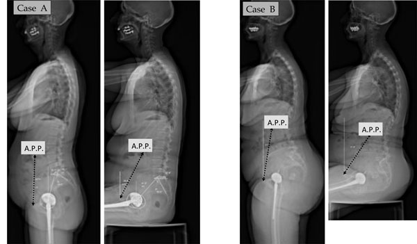
The APP or Lewinnek plane inclination in the standing (APPI-ST) and sitting (APPI-SIT) positions is defined as the angle subtended by a vertical reference line and a line tangent to the antero-superior iliac spines and the pubic symphysis. The variation of APP can be very significant from standing to sitting.
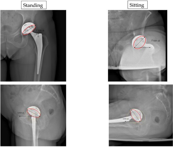
Comparison in standing and sitting positions for Frontal Acetabular Inclination angles (FAIA) on AP views and Sagittal Acetabular Inclination angles (SAIA) on lateral views.

Definition of the Sacro-Acetabular Angle (SAA). In this standard case SAA is 75°.
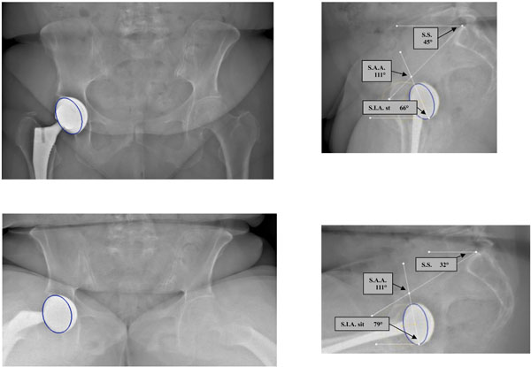
Abnormal SAA value: the cup is too vertical (SAA is 111°).
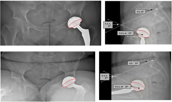
Abnormal SAA value: the cup is too horizontal (SAA is 47°).

A case with stiff lumbar spine and lumbo sacral junction: this patient is sitting as in a standing position (no reduction of lordosis for sitting and fixed anterior pelvic tilt or pelvic flexion) with potential anterior impingement.
A fused lumbo-sacral junction can induce impingement as the pelvis remains with the same tilt in standing and sitting position: the main adjustment parameter is the hips range of motion. These 2 patients are standing as in a sitting position (posterior pelvic tilt or pelvic extension).

A forward tilt of the pelvis (pelvis anterior rotation or pelvic flexion) as in standing position induces retroversion of the acetabulum, whereas a backward tilt of the pelvis (pelvis posterior rotation or pelvic extension) as in sitting position results in an anteversion of the acetabulum. The forward tilt of the pelvis is expressed by the low value of sacral slope (SS) in standing position, whereas the backward tilt is associated with a higher sacral slope angle.
EOS 2D measurements (A) using exclusively AP view underestimate the offset in comparison with 3D measurements (B, C) using the combination of AP and lateral views
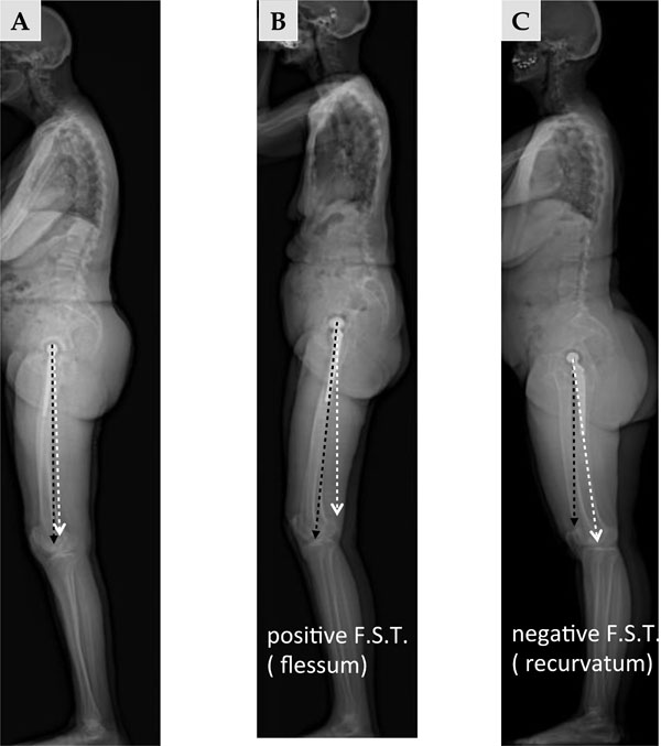
On the lateral view, the femoral sagittal tilt (FST) or femoral sagittal inclination angle is defined as the angle subtended by the vertical and the femoral axis between the center of the femoral head and Blumensaat’s line. A: standard patient in standing position. B: hip flexion in standing position. C: hip hyper extension in standing position.
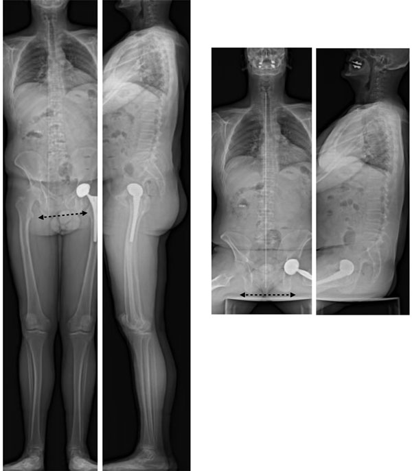
Comparison of standing and sitting AP views allows differentiation of oblique pelvis linked to lower limb discrepancy, as in the sitting position the frontal pelvic tilt disappears.
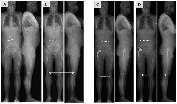
Analysis of limb length inequality. a- before surgery: without compensation (A) and with compensation to obtain a horizontal pelvis (B). b- after surgery: The THA procedure could not fully compensate the inequality (C) but the compensation needed is less (D) than in preoperative evaluation (B).

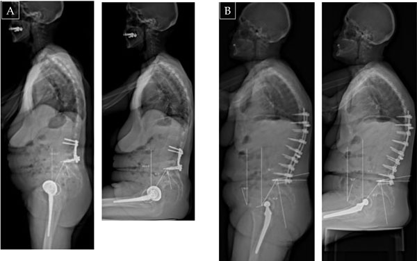
EOS comparison before and after left THA revision: correction of the length of the left lower extremity; the left flexion has disappeared.
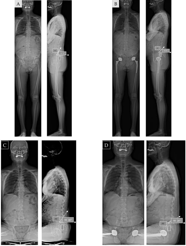
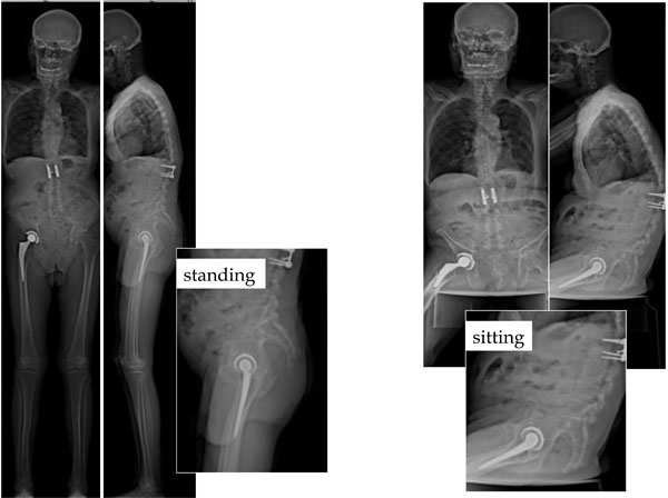
(A, B) EOS comparison before and after THA implantation: modification of pelvic balance in standing or sitting position (17° reduction of SS in standing position, 20° SS reduction in sitting position after THA in pelvic extension or backward pelvic tilt).

THA revision (in this case bilateral acetabular revision) can induce complex modification of the posture in the standing position but significant increase of pelvic extension for sitting position (decrease of SS from 26° to 7°).

Pelvic rotation in standing position (asymmetric projection of the iliac wings, with the posteriorized wing appearing thicker than the other): in this case the backward displacement of the left hip with THA induces a decrease in the cup anterior opening.
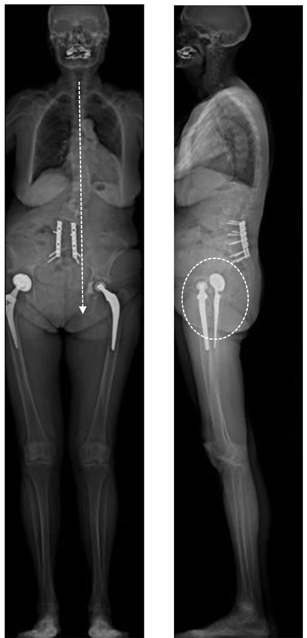
Bilateral THA case with thoraco-lumbar scoliosis (previous lumbo sacral fusion): Frontal imbalance in standing position is associated with significant pelvic rotation. On the lateral view the 2 femoral heads are not superimposed. One can observe the asymmetric projection of the iliac wings, with the anteriorized wing appearing thinner than the other: in this case the forward displacement of the left hip with THA induces an increase of the cup anterior opening (the patient experienced anterior subluxations in standing position).
Regarding the field of THA cases, the EOS imaging system provides coupled AP and lateral high-definition images in functional position, allowing the measurement of the pelvic parameters simultaneously with the acetabular and femoral parameters [12]. It has been demonstrated recently that EOS is accurate and reliable for the measurement of pelvic, acetabular and femoral parameters [13]. In addition, for the first time, full-body images can be obtained for more accurate analysis of current problems, including pelvic obliquity, spine deformity and imbalance, limb-length discrepancy, impingements and dislocations [14-16].
Here we describe the contributions of the EOS imaging technology to our standard practice in the context of our first 300 THA cases. In addition to data accuracy on the precise orientation of the implants in functional standing, sitting or squatting positions, this review paper discusses our experience with EOS imaging to study the hip-spine relationship and the practical impact of the detection of outliers and risky patients for THA complications. In particular, the analysis of complex postural situations will be addressed (association with scoliosis, leg-length discrepancy and frontal and/or sagittal imbalance). We will also discuss application of the EOS system for postoperative follow-up, especially for the assessment of postural changes induced by THA implantation.
MATERIAL AND METHODS
In this cohort study, 300 consecutive THA cases in 224 patients (174 females, mean age 68 years (range 34-90), mean BMI 29, 76 bilateral THA) were included from our routine practice for clinics consultation. 196 of the patients underwent primary. 117 of the cups were cemented polyethylene cups and the remaining 183cups were cementless. 183 of the stems were cemented.
For the evaluation of the standing position using the EOS® machine, each subject adapted a comfortable position, the reproducibility of which has been reported [17]. For the sitting position each subject adapted a comfortable position on a stool with adjustable height and backrest, hands on the knees and both feet flat on the floor. The results were obtained using the Stereos® software from EOS Imaging.
RESULTS
Hip-Spine Relations and Lumbo-Pelvic Parameters
- Although the concept of spino-pelvic balance is well accepted today [18-20], and although the hip is a highly mobile joint, surgical concepts are still based on the static AP view of the pelvis in standing or supine position to assess cup orientation with the measurement of the coronal inclination and the planar (or radiological) anteversion. The sagittal orientation of the cup using lateral radiographs is poorly documented [21], while the lateral view of the pelvis describes relevant parameters, namely the anterior pelvic plane (APP), pelvic incidence (I), sacral slope (SS) and pelvic tilt(PT), the variations of which significantly influence “normal” function and failures in THA [22, 23]. SS, PT and I are currently described as linked using the formula I = SS + PT (Fig. 2). This geometric relationship has been confirmed using simple regression models for standing position (PI=0,97 + 0,972 SS + 1,001 PT) and described recently for the sitting position (PI =0,985+ 1,021 SS + 0,972 PT) [12].
- Our results are reported in Table 1. In this series, the pelvic incidence I, which does not change with the posture, is 56° in average (SD: 12°; range 30° to 89°). The data are in accordance with the previous literature for standing position, the exploration of the sitting position remaining unusual despite its interest for some unstable THA [3, 6, 7, 13, 20, 23].
- The standing (ST) position involves a forward tilt of the pelvic block considered as pelvic flexion. This anterior rotation of the pelvis is sometimes described in aconfusing way as pelvic “anteversion” (Fig. 2). On lateral view, the sacral slope (SS-Sta) angle is about 40° (SD: 16°; range 33° to 63°) and the pelvic tilt (PT-Sta) is about 18° (SD: 11°; range 11° to 32°). For a given incidence angle, the pelvic tilt can be calculated as PT = I – SS [25]. One can observe a significant variation in standing SS when comparing this series to asymptomatic patients. The reduction of SS-Sta indicates a relativebackward tilt of the pelvis due to the ages of THA patients, as an associated aging spine is frequently observed [24]. This is in accordance with imaging and navigation measurements that have demonstrated changes in the sagittal balance of the spine over time with progressive pelvic posterior rotation in standing position and decreasing SS.
- In the sitting position (Fig. 2), the pelvis tilts backward during the transition to the sitting (Sit) posture; it is considered as pelvic extension. This pelvis posterior rotationis sometimes described in a confusing way as pelvic “retroversion”. Sacral slope (SS-Sit) diminishes to a mean of 20° (±12°), and sometimes as low as a negative value (-10°). Depending on the individual morphology and associated hip or spinal pathology, a variable degree of posterior pelvic tilt (PT-Sit) is observed (36° ±15°), with the sacrum more or less vertical. One can observe a greater dispersion of these parameters in the sitting position. Significant outliers can be observed in these measurements. Potential complications can be suspected in THA as unexpected functional orientation of the cups can be observed in some cases (Fig. 3).
- In the squatting position, pelvic posterior tilt (pelvic posteriorrotationor pelvic extension)is increased. Due to the fact that squatting position is not common among our population of Caucasian patients, we rarely explored this functional position. The decrease of SS can reach 10° more with a consequent equivalent increase of pelvic tilt increase due to the short acquisition time with EOS, this protocol can be realized even in aged patient with poor body stability. Due to the limitation of hip flexion in some individuals, the positioning of the hips can be asymmetrical, sometimes with atypical postures (Fig. 4).
- The variation in SS angle determines the range of PT, and this variation influences the orientation of the APP or the Lewinnek plane classically used as a reference for adjusting the position of the acetabular cup and for the postoperative evaluation of its orientation. (Fig. 5). The angular variations of the Lewinnek plane inclination between standing (APPI-ST) and sitting (APPI-SIT) are about 22°.
- In our experience the sitting position is more difficult to evaluate in obese patient. The APP measurement is mainly affected regarding the detection of the antero superior iliac process. We faced this problem in 10% of the cases in standing position (31 patients) and 19% in the sitting position (57 cases) with more than 5° (6 to 11°) in accordance with two successive measurements by two different operators.
Pelvic parameters in standing and sitting positions (300 THA cases).
| Standing | Sitting | |||||||
|---|---|---|---|---|---|---|---|---|
| Mean | SD | Min | Max | Mean | SD | Min | Max | |
| PT | 18,3 | 11,2 | -16 | 46,7 | 36 | 15,2 | 0 | 63 |
| SS | 40,01 | 10,1 | 9 | 74 | 20,4 | 12 | -10 | 55 |
| APPI (from 269 cases ) |
0,9 | 8,6 | -29,7 | 20 | 23 | 13 | -11 | 47 |
| APPI (from 243 cases ) |
||||||||
Results for acetabular inclination ( frontal and sagittal) in 300 cases.
| Standing | Sitting | |||||||
|---|---|---|---|---|---|---|---|---|
| Mean | SD | Min | Max | Mean | SD | Min | Max | |
| FAIA | 47,4 | 10,1 | 19 | 87 | 58 | 14,4 | 20 | 86 |
| SAIA st 260 THAs available (85%) |
41,3 | 16 | 0 | 92 | 53 | 15,2 | 16 | 84 |
| SAIA st 225 THAs available (75%) |
||||||||
Results for acetabular inclination ( frontal and sagittal) in 205 cases.
| Mean | SD | Min | Max | Mean | SD | Min | Max | |
|---|---|---|---|---|---|---|---|---|
| Anatomical anteversion |
34,7 | 15,4 | -15 | 58 | ||||
| Functional anteversion standing |
36 | 16,7 | -20 | 62 | 44 | 15,2 | -15 | 85 |
Functional anteversion sitting.
Acetabular Implant Position
- Three key parameters are considered for acetabular evaluation: frontal and sagittal inclination and acetabular anteversion. These parameters can be considered in two ways: as “morphological parameters” with reference to the bone frame of the pelvis as described by Murray in the lying position [25], and in relation to the “functional orientation” of the pelvis inducing significant variations in acetabular orientation and the values of these parameters in THA implantation for standing, sitting, squatting or pelvic rotation. In our current practice, we mainly use the “functional“ point of view, as the orientation of the body (and therefore the acetabular cup) significantly changes with functional position when comparing supine, standing and sitting postures as highlighted by the EOS imaging system. Whatever the position, the reference plane remains the horizontal transverse plane for all the measurements. The EOS imaging system provides 2D and 3D information regarding the acetabular orientation, but to date, we mainly use the 2D measures as they represented a good transition from our previous use of classical plane radiographs (Fig. 6).
Acetabular Frontal and Sagittal Inclinations
- Our results for frontal and sagittal inclinations are summarized in Table 2. One can observe some limitations for the measures on the lateral view. Globally, the measures could be done only in 260 cases for standing position (85%), and in 225cases in sitting position (75%). The main problem encountered has been the limitation induced by the 76 bilateral THA.
Only for 44 of these bilateral cases, a correct evaluation of the sagittal inclination angle could be obtained in standing position.Due to the superposition of the 2 cups, the measures could not be done in 32 THAs. The 44 remaining cases were more favorable due to a significant rotation of the pelvis inducing a gap between the 2 cups. In addition to these problematic cases, we faced difficulties in 9 obese patients (BMI >31).
In sitting position, the difficulties were more significant in 95 THAs (superposition of the 2 cups for 44 cases, difficulties for assessing the cup profile in 41 cases). - The relationship between the acetabular sagittal inclination angle (ISA) and SS is clear on lateral EOS images of the lumbo-sacral junction in standing and sitting postures. In the standing position, SS is high and acetabular inclination low. In the sitting position, SS decreases and acetabular inclination increases. On both lateral and AP views, the acetabular THA component is more vertical in the sitting position than in the standing position [1]. These variations in acetabular tilt contribute to the change in anterior opening of the acetabulum and thus in the orientation of the functional mobility cone of the hip joint.
- The coherence between sagittal acetabular tilt and SS is expressed by the sacro-acetabular angle (SAA), defined as the tangent of the sacral endplate and the axis of the acetabular ellipse on lateral view (the latter defining the angle of sagittal acetabular inclination to the horizontal). The SAA is fixed and empirically applied by the surgeon to the acetabular component in THA [6,20] (Fig. 7). Geometrically, SAA = SS +ASI. Our results demonstrate a wide variation of this anatomical parameter (mean 69°, range 31° to 129°). In this series, the consequences of poor adjustments in outlier cases induced atypical positioning of the cup and impingement situations in standing (12 cases) (Fig. 8) or sitting positions (14 cases) (Fig. 9).
- The lack of variation in PT between the standing and sitting positions (less then 5°) has been observed in 87 cases; it represents a loss of adaptability for the anterior acetabular opening, and the patient may have the same acetabular orientation in both sitting and standing positions (patient appears to stand in a "sitting posture"), which may induce posterior impingement. On the contrary, a fixed or stiff lumbo-sacral junction can induce an anterior impingement in the sitting position, as the standing posture of the pelvis remains with a specific forward pelvic tilt ( pelvic anterior rotation or pelvis flexion): we observed this situation more rarely (6 cases) (Figs. 10, 11).
Acetabular Anteversion
- The concept of acetabular anteversion (AV) is more confusing as two classical analyses of postoperative anteversion of the cup can be proposed: “radiological anteversion“ using plane X-rays (and then AP EOS images) and “sectional anteversion” using CT or Stereos software measures from EOS data. This confusion explains the heterogeneity of the literature regarding the data for the optimization of cup anteversion [26].
- Using the Pradhan technique [27] for the measurement of Radiographic Anteversion on EOS AP views, we previously reported [12] significant changes in the anteversion values between standing and sitting positions.Standing radiological anteversion was 17.2° (SD: 10.2 ; range -15° to 46.3°). In the sitting position, radiological anteversion was 35.4° (SD: 13.1; range 0.3° to -62.4°).
In addition, this study noted the questionable value of the Lewinnek safe zone, as the APP is not always vertical and cannot be systematically considered as the patient coronal plane for the determination of the “Lewinnek safe zone”. - CT is now the current gold standard for assessing the position of the implants [28].These measures are obtained in supine position, and only provide an instantaneous assessment of the “functional sectional anteversion” in supine position. Time-consuming reconstructions allow the evaluation of the “sectional anteversion” with reference to the APP. Because posterior dislocations of the hip mostly occur in the sitting position, and some anterior dislocations in the standing position [29], knowing the acetabular version in these positions could be important, and measuring cup version of the supine patient on a CT scan could result in misleading information as apparent acetabular anteversion increases 1° for every 2° increase of posterior pelvic tilt (pelvic posterior rotation or pelvic extension) [30,31].
- The notion of a relationship between sectional acetabular AV and the position of the pelvis has been previously reported in native hips [32] and in THA [33,34]. A forward tilt of the pelvis (pelvis anterior rotation or pelvic flexion) induces retroversion of the acetabulum, whereas a backward tilt of the pelvis (pelvis posterior rotation or pelvic extension) results in an anteversion of the acetabulum (Fig. 12). Lumbosacral junction mobility is the main parameter influencing the variations of AV between the standing and sitting positions. This parameter seems strongly relevant as degenerative phenomena in the aging spine induce progressive changes in sagittal balance with loss of lumbar lordosis and pelvic extension [18,19]. This evolution could partially explain the cumulative increase of dislocation risk with time [34].
- The EOS imaging system provides the measurement of the acetabular anteversion in a “sectional way” [9,13] according to the APP (and then to the pelvic frame, in a plane perpendicular to the APP) or in the horizontal plane of the patient allowing “functional measures” in standing and sitting positions. This direct approach of the functional sectional anteversion in the horizontal plane is a significant improvement for a more accurate analysis of THA complications (mainly dislocation or subluxation) [12]. Our results are summarized in Table 3 from 205 cases.
- We could observe the good correlation between the anteversion values measured in the horizontal plane in the standing position and those evaluated in the plane perpendicular to the APP. It is logical as in the majority of cases the APP is more or less vertical. On the contrary the values are completely different in the sitting position with a significant increase of the values due to pelvic extension(pelvic posterior rotation).
Femoral Parameters
Two parameters are routinely used for the evaluation of femoral implants: femoral offset and femoral anteversion. Two other parameters are interesting for the evaluation of the femoral orientation. The femoral version (or femoral tilt) in the AP view (adduction or abduction of the femur) and the lateral view is poorly documented, as the long-leg radiographs are rarely performed in current practice. In addition, the concept of cumulative anteversion (the sum of sectional acetabular anteversion and femoral anteversion) is considered a relevant but also poorly investigated parameter.
Femoral Offset
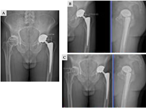
The importance of the offset restoration has been demonstrated. Due to the 2D nature of plain radiograph, the projection effect of the femoral anteversion and the external rotational contracture of the degenerative hip result in limited accuracy of plain pelvic radiographs. Plain AP pelvic radiographs could underestimate the offset value by 8% to 13% [35,36]. CT with 3D reconstruction can also measure offset and hip geometry, but it exposes the patient to significant radiation dose. Due to the simultaneous capture of two orthogonal AP and lateral images (like standard radiographs), low-dose EOS imaging provides the opportunity to compare 2D and 3D data in standing position, without additional imaging study. In comparison to standard radiographs and CT scans, it has recently been demonstrated that EOS is accurate and reliable without significant inconvenience caused by the metallic artifacts of implants [37]. According to our data on 100 patients, 2D measurements underestimate the offset by an average of 3.5 mm in implanted hips in comparison with 3D measurements (4.08 (± 0.76)/ 4.43 ( ± 0.70). The main factor explaining this discrepancy is hip rotational positioning, as the mean values for femoral anteversion were within the range previously published. These results are in accordance with previously published data about femoral offset and highlight the relevance of 3D EOS reconstructions (Fig. 13).
Femoral Sagittal Tilt (Femoral Sagittal Inclination Angle or Femoral Sagittal Version)
- On the lateral view, the femoral sagittal tilt (FST) or femoral sagittal inclination angle is defined as the angle subtended by the vertical and the femoral axis between the center of the femoral head and the summit of Blumensaat’s line [18] (Fig. 14). It is greater in case of flexion contracture of the hip in standing position, and can be negative in hyperextension of the hip. Femoral sagittal tilt correlates statistically with pelvic tilt: the greater the pelvic tilt, the greater the FST angle [20]. Generally the flexion contracture is mainly assessed clinically or qualitatively as the quality and feasibility of long-leg X-rays on lateral view is rarely sufficient to obtain precise angles and values.
- We analyzed the femoral sagittal tilt angle using the EOS lateral images of the whole series. The mean value for FST was 0.5° (SD 11.6° range -29.3° to 36.2°). The wide range of values was explained by some complex postural situations due to the interrelation of spine, hips and knees (limb length discrepancy, frontal imbalance, hip or knee flexion contracture). These values illustrate the compensation mechanisms to maintain an adaptive sagittal balance. Their interpretation was useful to understand anterior subluxation cases in 9 cases.
Femoral Anteversion and Combined Femoro-Acetabular Anteversion
- We measured the femoral torsions using the Stereos® software in 227 patients. Mean value was 12.7° (SD 15.2°; range: -42° to 33°). In 3 cases the high value of retroversion (-42°, -38°,-34°)was explained by a rotation of the femoral stem due to loosening. In 73 patients the measure was not possible due to the superposition of the femoral condyles in the lateral view. Then, the position of the patient during the acquisition of the standing position can be a limitation.
- Many studies have proposed optimal alignment of the acetabular cup. By contrast, only a few studies have dealt with optimization of the prosthetic alignment on the femoral side [38]. The concept of cumulative anteversion (CA) between the acetabular cup and the femur is considered a key factor to assess the appropriateness of overall prosthetic alignment to optimize the range of motion while avoiding prosthetic impingement and instability. This concept, however, is based on CT measurements in a supine position, which do not account for the functional dimension of the problem according to the standing or sitting position. For Jolles et al. [39] the dislocation rate increased 6.9 times in THA patients when the CA value was outside the range of 40° and 60°. Based on the results of computerized 3D model analysis, Widmer and Zurfluh [40] proposed the formula, cup AV + 0.7 stem AV, to calculate the CA value and considered the ideal value to be 37.3°. Yoshimine [41] proposed that the sum of the cup AV, plus 0.8 times the stem AT, plus the cup inclination should be 90.8° (AV + 0.8AT + RI = 90.8°). Hisatome and Doi [42] proposed that the sum of the cup AV plus 0.7 times the stem AV should be 42° (AV + 0.7AT = 42°) with a cup inclination of 45° for a head diameter of more than 32 mm.
- According to the good correlation between supine and standing measures of acetabular sectional anteversion, we calculated the cumulative anteversions using the standing measures by EOS. Mean cumulative anteversion was 42° (SD 20.5° range -23°to 77°). All of the 38 unstable THA in this series were outliers. The study of the cup orientation could clearly explain instability in 18 cases (7 anterior instability in standing position, 11 posterior instability in sitting position). In 11 cases, the analysis of the femoral torsion alone could explain the instability (4 anterior instability in standing position,7 posterior instability in sitting position). In 9 cases the combined analysis of acetabular and femoral anteversion was useful to explain the instability.
EOS imaging of THA in specific situations
THA and Leg-Length Discrepancy (LLD)
- Leg-length discrepancy after THA is frequently associated with general dissatisfaction and potential complications, but the magnitude of a clinically significant LLD after THA is still a matter of controversy. Numerous radiological methods for measuring LLD have been described but the results are variable with a diverging outcome. Although full-leg standing AP radiographs may provide a clear measurement of global and true LLD, they are not used frequently in daily practice. A standard AP view of the pelvis is used much more commonly to assess the preoperative and postoperative LLD, despite possible imprecision of pelvic radiographs because of changes in the position of limbs and pelvis. As a pelvic reference, both ischial tuberosities and the teardrops are used. On the femoral side, the lesser trochanter and center of the femoral head are used. LLD is expressed as the difference of the distance between a femoral and a pelvic landmark on both sides. Goodman et al. [43] recommended the use of the teardrop points as a landmark for measurements because the vertical positions of the teardrop points is not affected significantly by rotation of the pelvis. This pelvic evaluation provides information regarding the “projected anatomical length” of the superior part of the femurs but does not describe the functional position of the lower limbs. Functional limb length is the result of a complex interaction of the anatomic lengths of bones, implants, and also soft tissue contracture. An abduction, adduction, or flexion contracture should be assessed and quantified because of the potential influence on perceived length. A flexion contracture can lead to an overestimation of shortening. Common causes of a perceived long limb include scoliosis, fixed pelvic tilt, and contralateral limb deformity. Full-leg standing AP radiographs provide better information but limitations are due to the lack of lateral views analyzing the global sagittal posture. The degree of validity of CT is well documented, but CT can give only the anatomic length of the lower limbs without aiding assessment of the functional measurements, as the examination is performed in supine position.
- Using EOS full-body images AP and lateral, we were able to analyze 98 cases of “oblique pelvis”, flexion contracture or hyperextension of lower limbs: comparison of standing and sitting AP views allows differentiation of oblique pelvis linked to lower limb discrepancy, as in the sitting position the frontal pelvic tilt disappears (41 cases) (Fig. 15). On the contrary fixed oblique pelvis are not influenced by the sitting position. We could test the impact of heel compensation to correct LLD in 12 cases (Fig. 16) as well as the consequences of THA revision (Fig. 17).
Evolution of Pelvic Orientation After THA Implantation
- This issue is particularly controversial. Indeed the validity of preoperative planning and intraoperative navigation can be impacted by significant changes in the sagittal pelvic orientation postoperatively. The literature is not abundant on this topic because most postoperative controls rely on AP radiographs. CT scan reconstructions have focused on the pelvic bone reference frame regardless of variations in functional orientation in the sagittal plane. Some articles refer to changes in the anterior pelvic plane, but we know the problems associated with measurement uncertainties of the standard lateral view (obesity, pelvic rotation) [44, 45]. For others, the appreciation of the pelvic orientation is based on variations of the sacral slope, a more reliable benchmark that can be correlated with other pelvic parameters, including the morphological parameter of pelvic incidence.
- A classical adaptation mechanism has been describedfor flexion contracture of the hip related to osteoarthritis. The loss of extension capacity in the affected hip induces anterior pelvic tilt when the subject tries to stand. In this situation, the spine, when possible, adapts by increasing the lumbar lordosis. In these cases, THA implantation can improve the extension ability and a decrease of pelvic flexion(pelvic anterior rotation) can be noted. In other cases, a posterior pelvic extension(pelvic posterior rotation)can be observed. It is often associated with postural imbalance to compensate for a forward tilt of the trunk, especially with spinal aging. This postural adaptation verticalizes the acetabulum frontally and laterally, putting the hips in "upright hyperextension" with a potential risk for posterior impingement. This at-risk configuration may be aggravated by poorly adjusted lumbar fusion. A postoperative decrease of pelvic flexion (correction of pelvic anterior rotation) has been reported but without return to normal [5]. This phenomenon regarding the SS has already been described in the case of reduction of knee flexion contracture [46]. Other authors describe a progressive increase of the pelvic extension after THA over 2 to 4 years and mainly in older women [47]; this accords with the progressive spinal aging phenomena already described [24].
- We used the EOS® 2D images for the follow-up of 48 THA patients including 15 bilateral THA and 11 THA revisions (Figs. 18, 19). In standing position, we did not observe a significant change of sagittal tilt for 28 patients including 4 bilateral THA (group 1). Other patients experienced significant changes for sagittal pelvic orientation (group 2): an increase of SS (> 5°) in 7 cases and a decrease of SS ( >5°) in 13 cases. For sitting position, the group 1 did not experience changes in SS. For the other cases, changes were not related to those in standing position. Despite the postoperative alterations to pelvic orientation that could not be anticipated, none of these patients experienced an instability.
THA in Scoliosis Patients: The Influence of Pelvic Rotation
- This topic is poorly documented. However, a rotation or atypical pelvic tilt is frequently observed in scoliosis patients. Normal pelvic posture is classically defined on AP images in a subject in a strictly anatomic posture, with both iliac wings projecting symmetrically with respect to the longitudinal axis of the trunk. The standard criteria of sagittal balance are described on lateral views with both femoral heads perfectly superimposed. Pelvic rotation can be extreme in scoliosis involving the pelvic vertebra. The impact on acetabular orientation can be significant, due to altered functional anteversion in both standing and sitting postures [48]. In addition, some publications associate functional or anatomic LLD to pelvic torsion, but there is no clear consensus about the relation between the direction of ilium rotation and the observation of LLD [49, 50].
- The EOS® standing and sitting views of patients in their "normal or comfortable position" can detect this pelvic rotation with forward displacement of one side of the pelvis with corresponding backward displacement of the other side. On AP view, this is seen as an asymmetric projection of the iliac wings, with the anteriorized wing appearing thinner than the other. On lateral view, the two femoral heads and two iliac wings are not superimposed. Such “twisting” is hard to quantify on plain radiograph due to the conical spread of the radiographs, giving a misleading aspect to the femoral head more remote from the source. It is, in contrast, well analyzed on EOS® imaging in the standing and sitting positions, with good 3D visualization of the position of the pelvis [48]. Three-D reconstruction clearly shows how the forward displacement of one half of the pelvis with respect to the other increases the “forward opening” of the hip joint (increased functional anteversion of the acetabulum). Conversely, the relative backward displacement of the other semi-pelvis induces acetabular functional retroversion on that side (Fig. 20).
- We explored 30 patients (42 THA) with significant pelvic rotation (more than 10°). 12 patients had bilateral THA (24 hips). In these cases we could observe a significant asymmetry regarding the implants orientation in standing and sitting positions (Fig. 21).
CONCLUSION
Low-dose EOS imaging is an innovative slot-scanning radiograph system providing valuable data for the current practice of the THA surgeon as well as for spinal surgery. The simultaneous capture of two orthogonal AP and lateral images (like standard X-rays) while the patient is standing provides 2D and 3D measurements for the analysis of functional positions in THA patients. EOS has recently demonstrated accuracy and reliability in comparison to standard radiographs and CT scans, without significant inconvenience caused by the metallic artifacts of implants. We are aware of the limitations of this preliminary experience (limited number of patients, medical team with EOS experience) but some interesting information can be drawn.
For the first time, a global analysis can be performed in the true standing, sitting and even squatting positions. This innovative approach to the relationship between hip joint and spine, and even between knee joint and spine, is the manifestation of a postural strategy conditioned by anatomic and functional characteristics that can differ greatly from person to person.
The relation between the position of the spine and the acetabulum has a direct influence on the real functional range of motion of the hips. Anterior pelvic plane and sacral slope variations are relevant parameters for planning and navigation, but the comparison of standing and sitting positions demonstrates the importance of outlier detection. The EOS® imaging system provides valuable information regarding the pelvis functional anatomy in THA patients with clear applications for the study of unstable cases and potentially for the exploration of wear phenomena. Analysis of sagittal balance is relevant for the hip surgeon performing hip replacements in elderly subjects or in those with abnormal sagittal posture. This analysis must therefore be individual and integrated into the comprehensive evolution of the subject over time, because the phenomenon of an aging spine is frequently associated with the process of aging hips. New perspectives are open for more precise understanding of complex cases as limb length discrepancies or cases with pelvic rotation and obliquity as encountered in scoliotic patients.
CONFLICT OF INTEREST
The authors confirm that this article content has no conflict of interest.
ACKNOWLEDGEMENTS
Declared none.